Reducer Model Description

Dimensions of the Reducer
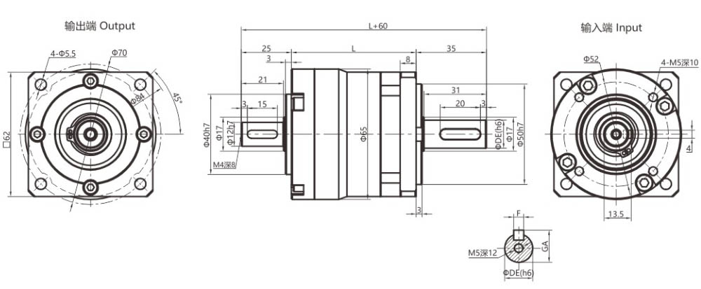
| Output Shaft Method | L | ||||
| DE | F | GA | Singel-stage | Dual-stage | Three-stage |
| Ø16 | 5 | 18 | 62 | 78 | 94 |
| Ø20 | 6 | 22.5 | |||
| Solid shaft output mode | |||||
| S(Shaft with key) | S1(Smooth output shaft) | T(Custom shaft) | |||
 |
 |
According to customers | |||
1. The input shaft diameter of model 60 is ≤17mm.
2. The output shaft diameter of model 60 is ≤ 17mm.
Reducer Ratio
| Series | Singel-stage | Dual-stage | Three-stage | |||||||||||||||||||||
| Ratio | Recommended | 16 | 25 | 28 | 60 | 100 | 125 | 200 | 250 | |||||||||||||||
| 3 | 4 | 5 | 7 | 10 | 12 | 15 | 20 | 35 | 40 | 50 | 70 | 80 | 140 | 175 | 280 | 350 | 400 | 500 | 700 | 1000 | ||||
| Not recommended | 30 | 100 | ||||||||||||||||||||||
| Normail Torque | Nm | 15.8 | 25.5 | 27.5 | 19.2 | 12 | 28 | 31.5 | 29.5 | 31.5 | 15.8 | 29.5 | 31.5 | 22.5 | 15.8 | 35.5 | 35.5 | 38.5 | 35.5 | 38.5 | 37 | 40 | 27 | 17.2 |
Reducer Parameters
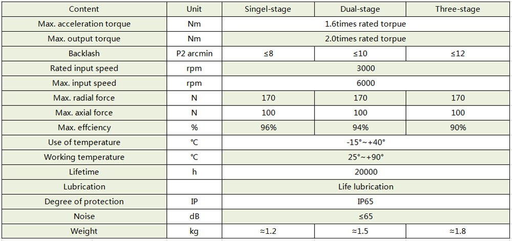
*1. Reduction ratio i=Nin/Nout(input speed/output speed).
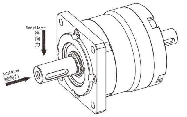
*2. When the speed of the output shaft of the reducer is 100r/min, it acts on the midpoint of the output shaft of the reducer, and the direction of action is perpendicular to the output shaft, meeting the maximum radial force that the output shaft can withstand when the life of the reducer is 20000H.
*3. High/low temperature grease can be customized according to the use environment.
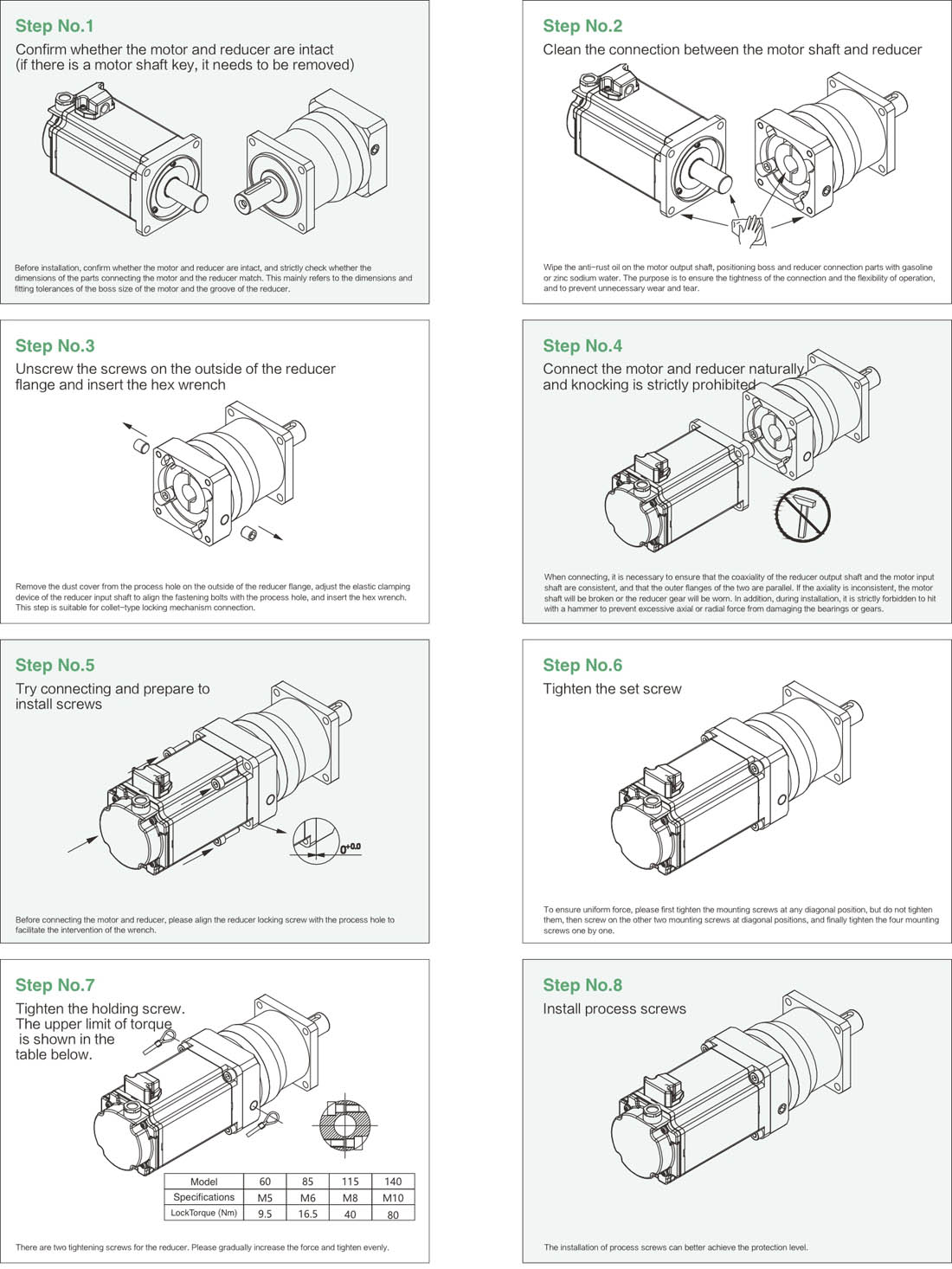
Install


 +86-18664078178
  Email
Email

